Interactive Projector System
In October 2017, Sony launched the Xperia Touch, a futuristic product that is both a projector and an Android tablet – it uses an infrared sensor to convert any flat surface to a touch screen. However, it comes with a hefty $1700 price tag. What if I tell you that most of its functionalities can be achieved with a $50 Kinect Sensor and some computer vision techniques?
Note: This is a project I worked on in 2016. Unfortunately the source code was lost when the SSD of my MacBookPro failed (I didn’t know anything about Git back then). So I will only discuss the high level ideas here and leave the implementation up to you.
What you Need
- A camera with a depth sensor (preferably a Microsoft Kinect since it offers a wider range of depth perception than other sensors like Intel RealSense, at the cost of lower resolution.)
- A projector. This system works best with a < 120 inch display.
- OpenCV + programming language supported by your depth sensor’s SDK.
The environment I used was OpenCV 2.4.9 + Microsoft Kinect Gen 1 + Visual C++. It’s really outdated so feel free to use the latest versions of hardware and software.
System Architecture
Before we dive into details, let’s take a look at the system architecture.
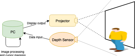
As shown in the figure above, the system consists of a PC, a projector, and a depth camera. The depth camera captures RGB and depth images of the projection area and sends them to the computer. The computer then processes the images and respond to touch/swipe gestures. The projector, as its name suggests, faithfully projects anything the computer tells it to.
The reason why we use a depth camera instead of a regular ol’ color camera (plus some fancy detection algorithms) has to do with robustness. Here’s an adversarial example to convince you why color cameras won’t work: imagine projecting a photo of a person pointing at something. Despite having no user in front of the screen, the computer would see a person in its view and respond to it. There are also many technical hurdles of recognizing a human hand under various lighting conditions and detecting touch gestures which only induce miniscule frame-wise difference on 2D images. By using a depth camera we introduce an extra dimension, which gives us additional information to work with.
Flow Diagram
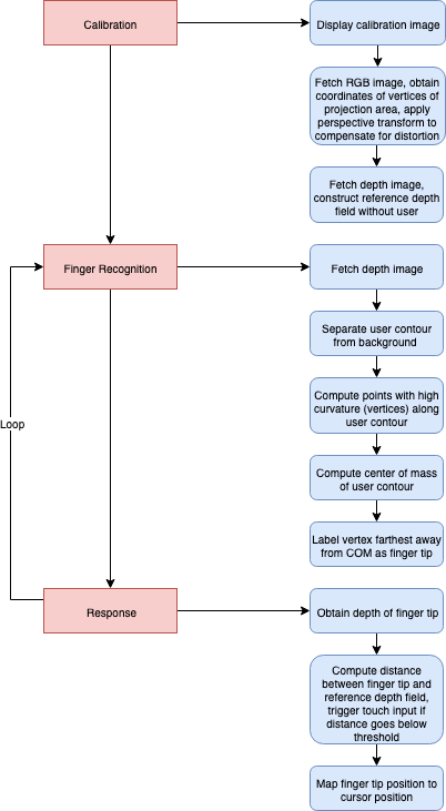
Here’s a flow diagram of the entire system, just to provide an overview.
Details
1. Calibration
Since the camera has a field of view larger than the projection area and is usually placed with an angle to the level surface, we need to do some calibration beforehand. First, we need to extract the four corners of the projection area from a frame of color image. Instead of using raw edge detection, which is unreliable under uncertain lighting condition, we can display a custom calibration image full-screen. The calibration image I used has four distinctive red dots at its four vertices:
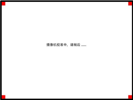
Then we can use simple thresholding to obtain the camera coordinates of the four corners. The threshold can be empirical. An alternative is to implement an interface which lets the user mark the vertices manually.
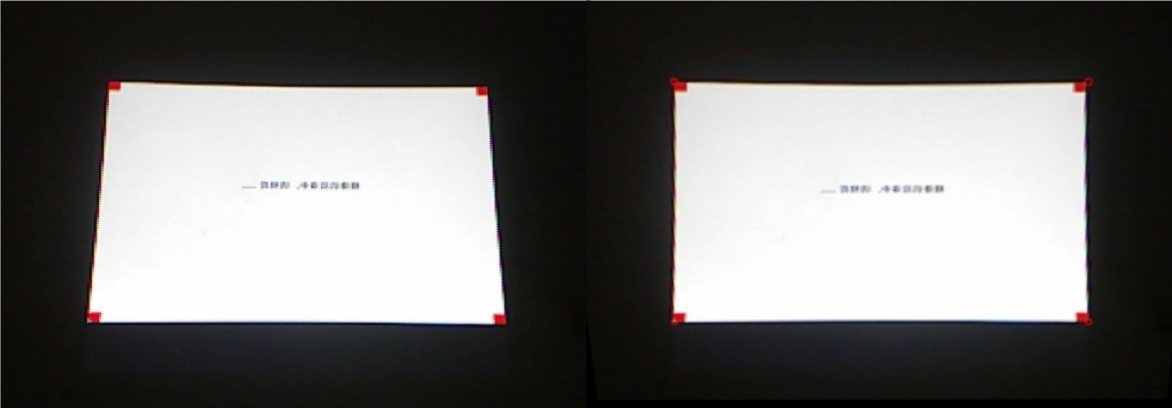
The next step is to correct the distortion. Since the camera is placed with an angle to the level surface, the projection area is usually captured as a trapezoid or a quadrilateral. Applying perspective transform, we can get a rectangular projection area which is more convenient for cursor mapping. On a high level, a perspective transform is as follows:
\[[x'~~y'~~w] = [u~~v~~1] \begin{bmatrix} a_{11} & a_{12} & a_{13} \\ a_{21} & a_{22} & a_{23} \\ a_{31} & a_{32} & a_{33} \end{bmatrix} \\[2ex] [x~~y] = [\frac{x'}{w}~~\frac{y'}{w}]\]where \((u, v)\) is the coordinates of a vertex in the original system and \((x, y)\) is its coordinates in the new system. Note that the goal here is to get the transformation matrix so that we can apply it to future frames. We already have the original camera coordinates of the corners. To get the new coordinates, we can use the top-left corner as a reference point and adjusted the other 3 corners to form a rectangle. Then, the transformation matrix can be easily obtained using getPerspectiveTransform() function in OpenCV. Alternatively, we can also directly solve for the transformation matrix using SVD.
The last thing we need to do at the pre-processing stage is store a matrix of “reference” depth. That is, before the user enters the frame, we record the depth value of each pixel in a matrix. This will come in handy later on.
2. Finger Detection
This is the main stage of our program. At this stage, the user can interact with the projection area. On the software end, when we receive a frame of depth image (encoded as a grayscale image), we compare it with the reference depth matrix. Taking the difference between the two, we obtain an user-only image in which all pixels are close to zero except the ones representing the user. Then, we proceed to detect the fingertip via contour detection, curvature, and image moment. The main idea is that a fingertip resembles an protrusion along the user contour, and that it’s usually far away from the centroid of the contour.
We start by using an OpenCV built-in function findContours() to get the user’s contour from the user-only image. The function uses the algorithm proposed by Suzuki in this paper. Note that some sort of noise reduction is necessary due to the low precision of the depth sensor. Having extracted the user contour \(C:p_1p_2 \cdots p_n\), we compute the curvatures along \(C\). Starting from \(p_1\), in each iteration we take three pixels
and construct vectors \(\overrightarrow{AB}\) and \(\overrightarrow{BC}\). The intervals \(i\) between \(A\), \(B\), and \(C\) should be linearly related to user’s distance from the camera. Let \(d\) denote \(\overrightarrow{AB} \cdot \overrightarrow{BC}\) and \(c\) denote \(\overrightarrow{AB} \times \overrightarrow{BC}\). Then \(d\) and \(c\) can be computed as follows:
\[d = (b_x - a_x)(c_x - b_x) + (b_y - a_y)(c_y - b_y) \\ c = (b_x - a_x)(c_y - b_y) + (b_y - a_y)(c_x - b_x)\]where \(\|d\|\) tells us the amplitude of the angle between these vectors, i.e. the approximated curvature at point \(B\), and the sign of \(c\) tells us the orientation of this curve, i.e. whether it is pointing inwards or outwards. After traversing the contour, we can put all protruding sharp points with \(\|d\| \geq i^2/2\) and \(c < 0\) in a set of candidates. The threshold \(i^2/2\) is empirical and works well in practice.
Finally, we identify the candidate farthest away from the centroid of the contour as the effective finger tip. In OpenCV, the Moments class has a function moments(), which computes the central moments of order up to 3. The location of the centroid can be computed using the following formula:
where \(m_{00}\) is the area of the contour and \(m_{10}, m_{01}\) are the central moments of the first order.
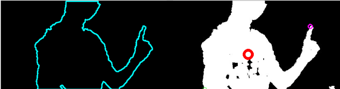
The figure below shows a typical result of finger recognition. The red circle indicates the centroid of the contour, the pink circle indicates the effective finger tip, and the green circle is an eliminated candidate.
3. Response
Having obtained the position of the finger tip, we then compare its depth with the reference depth field. Their difference, \(d\), is the distance between the user’s finger tip and the projection surface. If \(d < 30mm\), then trigger LEFTDOWN (press left button) event. If \(d\) goes above \(30\)mm again, then trigger LEFTUP (release left button) event. Together, the two events simulate a mouse click. If \(d\) stays below \(30mm\) and the finger tip moves around, then a swipe event is triggered.
After a mouse event is triggered, we need to map the coordinates of the finger tip in the camera system to those of the cursor in the monitor system. This can be achieved via simple linear transformations, which I will not elaborate here.
Conclusion
Along the way of doing this project, I realized that it has several limitations. For instance, we can’t detect the finger tip when it’s obstructed by the user’s body, and the camera is assumed to be fixed after calibration. Additionally, the fact that the algorithm is based on traditional computational geometry techniques makes it less robust than, say, a machine learning model. However, I still find it worth posting here because it shows how the combination of simple techniques can achieve great functionalities.
Thanks for reading ;).